Paneling in Rhino – FlowAlongSrf vs Paneling Tools plug in
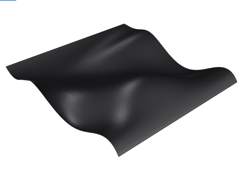
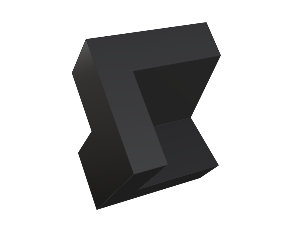
Create a surface of interest to use as a base to “panelize” one modular element. I used boolean operations to create a module for paneling the surface.
In order to get base plane for the polysurface, create a boundingBox around it. Then extract the bottom surface of the resulting box and delete the rest of the box. Flip the base plane’s surface normal direction (dir). We want the base plane to be slightly larger than the arrayed polysurfaces to avoid badly formed surface edges at points of infinite surface curvature:
Perform the flowAlongSrf command. Make sure that the surface UVW directions match between your base surface and your target surface.
 (1)")
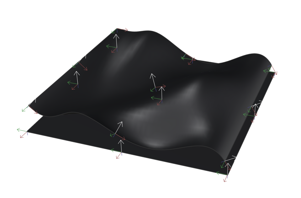
Paneling Tools – To “panelize” the surface you will first need to create point grids. Use the surface/s created in step 01 and experiment with different grid options.
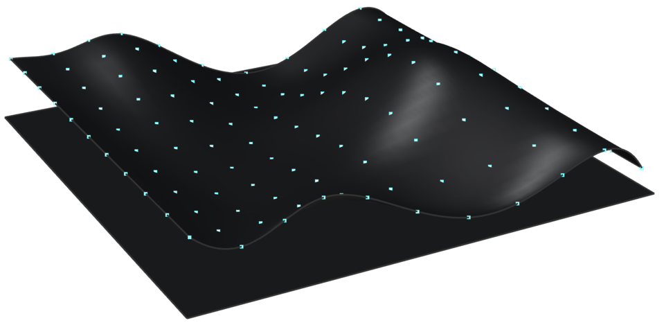
Go to Paneling Tools > Create Paneling Grid > Surface Domain Number and select your surface. (ptGridSurfaceDomainNumber)
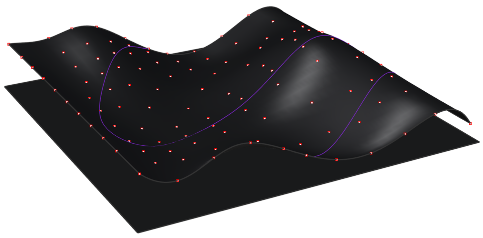
Go to Paneling Tools > Create Paneling Grid >Surface Domain Variable and create a grid based on curve attractor.(GridSurfaceDomainVariable)
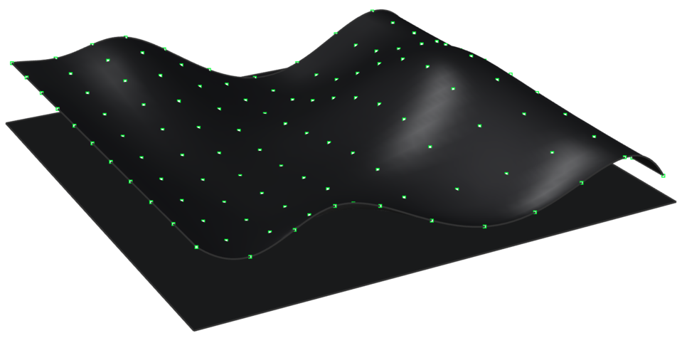
Go to Paneling Tools > Create Paneling Grid >Surface Domain Variable and create a grid based on point attractor. (GridSurfaceDomainVariable)
Select one of the grids and surface experiments from prev step.
Go to Paneling Tools > Grid Utility> Offset Points and offset your points with distance method Fixed.
")
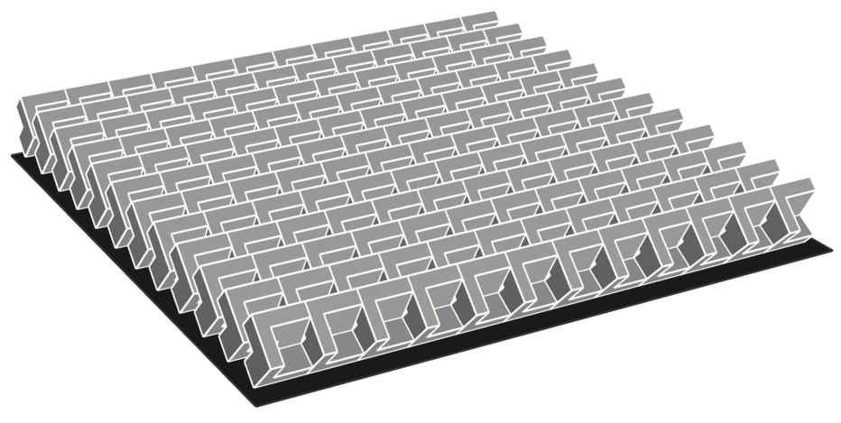
To populate the point grids with your Custom module, go to Paneling Tools > Paneling from Grid >Panel Custom 3d. When you are asked for 2 bounding surfaces press Enter for none. Or select the base created previously. When you are asked to select objects do not select your entire polysurface array – just select one polysurface. Rhino will preview the adjacencies of the panelling, then press Enter to accept.
")
Experiment more with attractor points or curves and more than one Population Polysurfaces. Paneling Tools > Paneling from Grid >Panel Custom 3d Variable